Projects
Below is a detailed summary of the technical projects I have completed as an undergraduate research lab assistant and intern, as well additional work I have done throughout my high school and college career in classes.
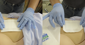
Wound-Dressing Robotic System
Human and Robot Partners Lab (CMU), Robotic Caregiving and Human Interaction Lab (CMU)
I established the motion requirements and design recommendations for a wound-dressing robot via data analysis, informing the design of a wound-dressing end-effector. Currently, I am iteratively designing and prototyping a compliant end-effector for a wound-dressing robot. I also researched and identified gaps in existing machine learning segmentation models for wound detection.
Computation of Human Centroidal Dynamics
RoboDesign Lab (UIUC)
I am using human-machine-interface (HMI) data to compute a reduced-ordered model, specifically the centroidal dynamics model, in real-time for a human pilot. This model will be used to investigate human motion and balancing strategies to inspire robot control.

HOPPY Simulation
RoboDesign Lab (UIUC)
I applied robot dynamics and controls principles, including finite-state machines, Jacobians, and trajectory planning, to begin creating an accurate dynamic model of HOPPY, a robot that jumps around a fixed gantry. I employed the software program MuJoCo to simulate the model and HOPPY’s movement within the gantry environment.

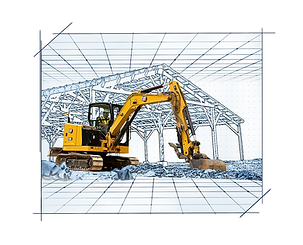
360-Degree Camera System
Caterpillar
To enhance the operational efficiency and safety of Mini-Hydraulic Excavators (MHE), I was tasked with researching 360-degree camera system options, comparing and implementing them. I installed both the Caterpillar Work Area Vision System (WAVS), an aftermarket camera system, and a prototype low-cost alternative system. Part of the process included determining where cameras should be placed, evaluating whether or not ISO 5006 standards were met, establishing if there were any blind-spots, and communicating with the aftermarket engineers any issues I faced or feedback I had.

Boom Swing Sensor System
Caterpillar
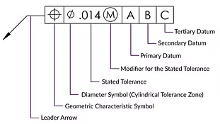
Caterpillar's Ease of Use program for Mini-Hydraulic Excavators (MHE) references a group of sensors placed on machines to provide visual and audio aids for the operator. For example, one of the features the Ease of Use program offers is E-fence. E-fence sets up walls around the machine that prevent the boom and swing from going past a certain point. If a building is next to the machine or there are pipes underground, E-fence allows the user to set boundaries that stop the machine from getting close to them. For E-fence and the Ease of Use program's other features to work, specific sensors must be placed on the machine to measure the variables of interest. One of these sensors is the boom swing sensor, which measures the rotation of the boom (what angle it is at). However, there are some inaccuracies with the boom swing sensor. There was a target angle error set, but it was being exceeded by a significant amount. The project's objective was to determine this issue's root cause.
To begin with, tolerance analysis was done on the linkage connecting the sensor placed on the machine to the boom swing we are measuring the rotation of. CLINK, a linkage model analysis tool, was used to simulate the full rotation of the boom, taking into account the worst-case conditions in regard to positional tolerance and clearance of the linkage, to determine the angle error (in other words, how badly could this linkage be manufactured and how much does this affect angle error?). This analysis concluded that there was a large amount of tolerance stack-up in the linkage design, resulting in a high angle error. The primary sources of angle error (specific features of the linkage design) were determined as well.
The next step was modifying the linkage design in Creo, creating a new CAD model and engineering drawings. The tolerances present in the initial design were already relatively small; therefore, simply reducing the tolerance values to decrease the tolerance stack-up was not sufficient. Whole parts of the design required changing. At the same time, we needed a design that was also manufacturable. To ensure this, I talked with suppliers, gathering feedback on possible design changes that could be made. The new design was finalized and sent to be manufactured; it will be tested to confirm if it solved the issue.

Medical Training Arm Simulator
The Human Dynamics and Controls Lab (UIUC)
Rigidity is a movement disorder that is characterized by an abnormal increase in muscle tone (which is the stiffness or resistance to movement of a muscle). This condition, which is often seen in patients with Parkinson's disease, may interfere with one's movement and can result in some pain or discomfort.
To evaluate rigidity, clinicians move their patients arm up and down, extending/stretching it, to determine whether the stiffness/resistance is abnormal or not (as shown in the video).
This process, however, is subjective and depends on a clinician's experience. Additionally, when medical students are learning about this condition, along with being told its definition, they may get to conduct the evaluation assessment themselves on patients experiencing rigidity. As explained previously, though, this may cause patients pain and students may repeat the evaluation several times to ensure they are doing it correctly, possibly harming the patient more. In hopes of standardizing this procedure and also avoiding causing pain to patients through this assessment that may feel invasive to them, the arm trainer team at HDCL is creating a robotic simulator that would mimic different levels of rigidity, as well as other neurological behaviors, to help medical students and other healthcare trainees practice and improve their clinical techniques. Other behaviors include spasticity (which is similar to rigidity, but is dependent on the stretch velocity) and cogwheel rigidity (which is another type of rigidity but deals with tremors).
My primary role on the arm trainer team was to revise the existing shroud CAD (the shroud are the 3D printed parts surrounding the arm trainer). You can see the CAD in the picture. I found that the previous design was not secure enough and assembly/disassembly was difficult. It required several bolts for installation and having to drill and tap holes in areas that were very thin and not sturdy enough to hold all the shroud together. My goal was to optimize the number of connections and fasteners to facilitate manufacturing and assembly. I used SolidWorks when revising the CAD, doing multiple iterations, and 3D printing (used Cura) low percentage prototypes to evaluate their efficacy, ultimately doing final prints of the shroud for the arm trainer/simulator, as seen in the photo.
The next step will be to start conducting the study, gathering clinicians and seeing how accurate the trainer is.


Hand Crank Power Bank
ENG 177 (GFX Project Scholars)
The goal of this project is to provide relief to natural disaster survivors who are suffering from energy inaccessibility by developing a hand-powered generator that converts kinetic to electrical energy. We have created a CAD model for the generator and, after evaluating other products that utilize kinetic to electrical energy conversion, have begun ordering materials to construct the power bank.

Smartphone and Headphone Charging Case
ME 170
We delivered a "ready to manufacture and market" design specification for a multi-use phone case that can simultaneously charge a smartphone and bluetooth headphones. Concepts such as human-centered design were employed to develop a product that meets consumer's unmet needs, and tools like Autodesk Fusion 360 and aPriori were utilized for optimization.
Moreover, my group was awarded the "ME170 Outstanding Achievement Awards for Excellence in Engineering Design" from the Department of Mechanical Science and Engineering following the completion of the project.
Sinking Oil Detection
Engineering Senior Research Project
Unable to evaporate or dissolute when submerged, sinking oil spills have a severe, long-term impact on wildlife and the environment and cleaning out this oil from the bed of a water body can cause more harm than good. There is one solution available, an autonomous underwater vehicle (AUV) that utilizes a laser fluorosensor to detect oil slicks, but it can not sense most sinking oils.
This project aimed to establish an alternative sensor that can detect sinking oil spills, testing its efficacy in an AUV through simulations in ANSYS Discovery. First, differential variables for water and sinking oil spills (values that are different for water and sinking oil) and the respective sensors that can measure them were identified. The AUV was then constructed in SpaceClaim. In ANSYS Discovery, I created a testing environment in which I simulated the AUV and measured what values were outputted for water versus sinking oil. If the difference in values was large enough, I considered the respective sensor as a possible alternative sensor for detecting sinking oil spills.


Myoelectric Sensor Prosthetic Hand
Biomedical Engineering Research Project
My team and I designed a prosthetic hand prototype in Autodesk Inventor for military amputees. We used Arduino to link a myoelectric sensor, a sensor that detects the electrical signals from one's nervous system, to a tension system with servo motors that control finger movement.
Smart Walking Stick
Solar Panel Research Project
My partner and I prototyped a solar-powered walking stick for visually impaired people. It utilized an ultrasonic sensor, which detects distance using ultrasonic sound waves. If the user was a certain distance away from an object, a vibrating miniscule motor disc, at the top of the walking stick where their hand would be, went off to alert them of obstacles.
